PRO_ 2018 Ford Explorer Test and Replace the Catalytic Converter to fix DTC P0430
Introduction
The Catalytic Converter is a component of a vehicle's exhaust system, required to meet current environmental regulations and standards. Its purpose is to reduce harmful emissions before they are released into the atmosphere. However, when the Catalytic Converter malfunctions, it can lead to issues affecting engine operation, fuel efficiency and emissions, often causing Diagnostic Trouble Code (DTC) P0430 to set. This guide will assist you in diagnosing and replacing the Catalytic Converter to effectively resolve DTC P0430 in 2018 Ford Explorer V6 3.5L models.
What is DTC P0430?
P0430 – Catalyst System Efficiency Below Threshold (Bank 2)
DTC P0430 indicates the Bank 2 Catalyst system efficiency is below the acceptable threshold. To evaluate Catalytic Converter efficiency, the Engine Control Module (ECM) calculates the oxygen storage capacity of the Catalytic Converter while performing active air fuel ratio control over 10 to 20 second tests. This calculation is based on the comparison result of the voltage output of the Heated Oxygen Sensor (HO2S) and calibrated the HO2S value. If the result is below 0.4 mv, it indicates optimal oxygen storage capacity and effective hydrocarbon (HC). If the measured value fails to meet a specified threshold, it signifies potential failure of the Catalytic Converter. In response, the Malfunction Indicator Lamp (MIL) is illuminated, and a Diagnostic Trouble Code (DTC) such as P0430 is set. Many factors can contribute to this DTC, such as malfunctions in the Oxygen Sensor (O2S), fuel injector, or damaged turbocharger, but a damaged catalytic converter is frequently indicated.
Initial Inspection
Before diagnosing the Catalytic Converter, check for exhaust leaks or damaged components in the exhaust system. Inspect the oxygen sensors and wiring for signs of damage or deterioration. Additionally, verify the integrity of the exhaust manifold and ensure there are no restrictions in the exhaust system.
Refer to the Vehicle Emissions Warranty Manual for time and mileage coverage of emissions-related fault(s). For additional information, refer to the Service Manual or applicable Technical Service Bulletin (TSB).
Diagnostic Procedures
Step 1: Turn the ignition to the key ON engine OFF position, and connect an Innova Scan tool to the Data Link Connector (DLC). Access the Powertrain Control Module (PCM) and monitor the Low Side Fuel Pressure PID.
If the measured value is in the 77 – 89 psi (156 – 182 inHg) range, proceed to Step 2.
If this value is not within specification, repair the Fuel Delivery system and perform Repair Validation.
Step 2: Check the Exhaust system for leaks. NOTE: High-pressure air can damage the exhaust system components. Adjust the air supply to 5 psi (10.2 inHg) before applying to the exhaust system.
Apply air pressure into the exhaust system through exhaust pipe.
Check leaks in the exhaust system using a solution of soap and water.
Apply the soap solution to following area:
The exhaust flanges and gaskets
The upstream and downstream HO2S and mounting surface
The exhaust system between the upstream and downstream HO2S
Check correct torque of upstream and downstream HO2S, exhaust flange.
NOTE: Torque: 35 lb.ft (48 Nm)
If there are leaks, repair and perform Repair Validation.
If no leaks are present, proceed to Step 3.
Step 3: Drive the vehicle in stop-and-go traffic conditions. Decelerate at closed throttle and then accelerate from each stop moderately. Drive the vehicle in 5 different cruise speeds, ranging from 25 to 45 mph (40 to 72 km/h) over a 10-minutes period. After driving, proceed to Step 4.
Step 4: Perform the Repair Validation.
If DTCP0430 is still present, replace the Catalytic Converter with a new one. Perform the Repair Validation.
If DTC P0430 is not present, the test is completed and there are no further issues.
Replace The Catalytic Converter
Removal
Step 1: Place the vehicle on lift with transmission in the Neutral position.
Step 2: Remove the Engine cover with two retainers.
Step 3: Disconnect the HO2S connector on the left side.
Step 4: Remove four bolts and the heat seal.
NOTE: Tighten the bolts to 89 lb.in (10 Nm) when installing.
Step 5: Remove the top Catalytic Converter retainers.
NOTE: Replace the retainers when installing.
Step 6: Disconnect the Catalytic Monitor Sensor electrical connector.
Step 7: Raise vehicle for access then remove the exhaust Y-pipe.
Step 8: Remove the lower Catalytic Converter retainers.
NOTE: Replace the retainers when installing.
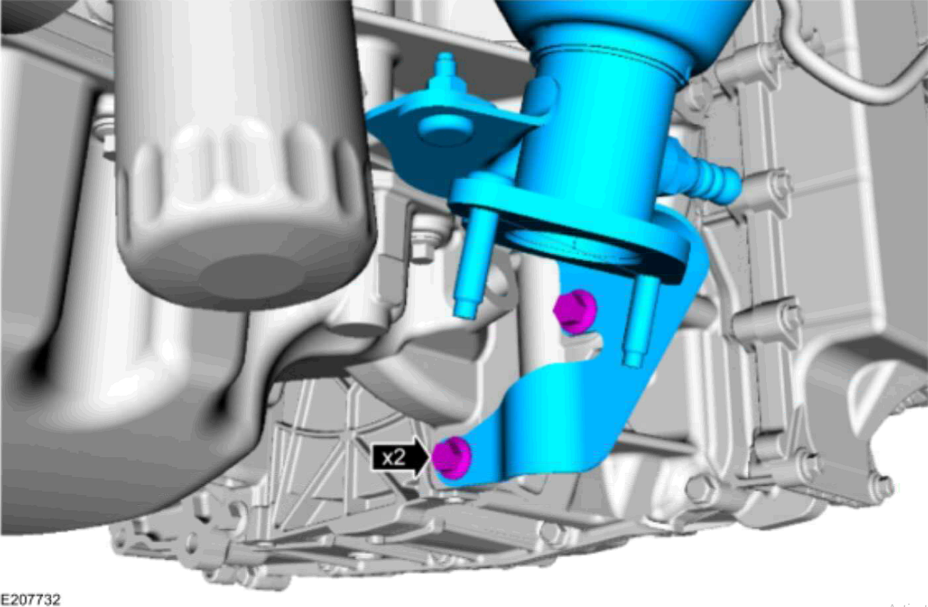
Step 9: Remove the two Catalytic Converter bracket bolts, and remove the Catalytic Converter. NOTE: Tighten the bolts to 35 lb.in (48 Nm) when installing.
Step 10: Remove and discard the Catalytic Converter gasket and the studs.
NOTE: Tighten the studs to 106 lb.in (12 Nm) when installing.
Installation
Installation is accomplished in the reverse order of removal. Tighten fasteners as specified above.
NOTE: Tighten the Catalytic Converter nuts in 2 stages:
Stage 1: 18 lb.ft (25 Nm).
Stage 2: 18 lb.ft (25 Nm).
Repair Validation
1. Clear Diagnostic Trouble Code (DTC(s)) and Freeze Frame (FF) information.
2. Perform the Key ON Engine OFF (KOEO) and Key ON Engine RUNNING (KOER) tests or follow the On-Board Diagnostics (OBD II) drive cycle requirements for the fault area.
3. Optionally, operate the vehicle within the conditions recorded in the FF data.
4. Check for pending or stored DTC(s). If none are found, the repair is complete.