2010-2017 Chevy Equinox Test and Replace the Catalytic Converter to fix DTC P0420
Introduction
The Catalytic Converter is a component of a vehicle's exhaust system, required to meet current environmental regulations and standards. Its purpose is to reduce harmful emissions before they are released into the atmosphere. However, when the Catalytic Converter malfunctions, it can lead to issues affecting engine operation, fuel efficiency and emissions, often causing Diagnostic Trouble Code (DTC) P0420 to set. This guide will assist you in diagnosing and replacing the Catalytic Converter to effectively resolve DTC P0420 in 2010-2017 Chevy Equinox L4-2.4L models.
What is DTC P0420?
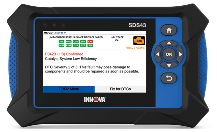
P0420 – Catalyst System Low Efficiency
DTC P0420 indicates an issue with the Catalytic Converter, often triggered by monitoring the post-catalyst HO2S response. During each drive cycle, the Engine Control Module (ECM) monitors the post-catalyst Heated Oxygen Sensor (HO2S) response. Ideally, the post-catalyst HO2S signal should be significantly lower than the pre-catalyst HO2S signal when extra fuel is added. However, if these two signal values are too close, it suggests that the Catalytic Converter efficiency may be compromised. In such cases, the ECM sets DTC P0420, indicating the need for further inspection and potential replacement of the Catalytic Converter.
Initial Inspection
Before diagnosing the Catalytic Converter, check for exhaust leaks or damaged components in the exhaust system. Inspect the oxygen sensors and wiring for any signs of damage or deterioration. Additionally, verify the integrity of the exhaust manifold and ensure there are no restrictions in the exhaust system.
Refer to the Vehicle Emissions Warranty Manual for time and mileage coverage of emissions-related fault(s). For additional information, refer to the Service Manual or applicable Technical Service Bulletin (TSB).
Diagnostic Procedures
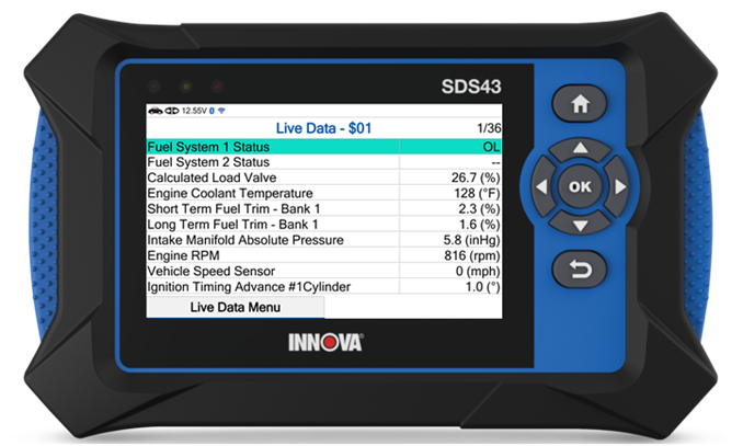
Step 1: Start the engine and allow it to idle. Use an Innova Scan Tool to monitor the Engine Coolant Temperature sensor (ECT). The value in Live Data mode must be between 185-221°F (85-105°C).
Step 2: Use an Innova Scan Tool to access the Live Data (LD) function of the Engine Control Module, then observe the Fuel Trim at idle. These values are greatly influenced by vacuum leaks. Inspect the Long-Term Fuel Trim (LTFT) at idle, 1500, 2000, and 2500 RPM. The values should be less than +/- 10%.
- If the value is greater than +/- 10%, correct the problem before continuing. Check for fuel pressure issues, leaking injectors, vacuum leaks, Mass Air Flow (MAF) sensor faults, etc.
- If the value is within specification, proceed to step 3.
Step 3: Increase engine speed to 2000 RPM and maintain for approximately 3 minutes. Make sure Closed Loop operation is achieved.
Step 4: Return the engine to idle. Using a Scan Tool in Live Data (LD) graphing mode, monitor HO2S Bank 1 Sensor 2 voltage. The voltage should slowly fluctuate near 0.45V.
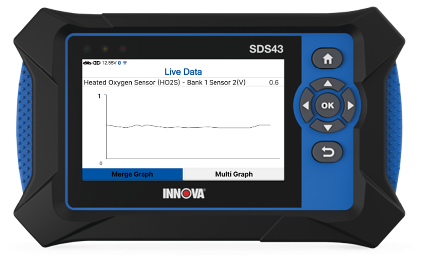
- If the voltage is fluctuating rapidly between 0.1–0.8V, a defective Catalytic Converter may be indicated. Before replacement, check for misfires, over-fueling, physical damage, etc.
- If the voltage did not follow this pattern, replace the HO2S sensor, then perform Repair Validation.
- If the same DTC sets, perform Repair Validation.
Replace The Catalytic Converter
Removal
Step 1: Use a lift to raise the vehicle as required.
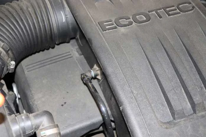
Step 2: Remove the air cleaner outlet duct with two resonator clamps.

Step 3: Remove the 3 bolts and remove the Exhaust Manifold Heat Shield.
| Remove the 3 bolts and remove the Exhaust Manifold Heat Shield. | |||
| Remove the 3 bolts and remove the Exhaust Manifold Heat Shield. | Remove the 3 bolts and remove the Exhaust Manifold Heat Shield. | | |
| Remove the 3 bolts and remove the Exhaust Manifold Heat Shield. | Remove the 3 bolts and remove the Exhaust Manifold Heat Shield. |

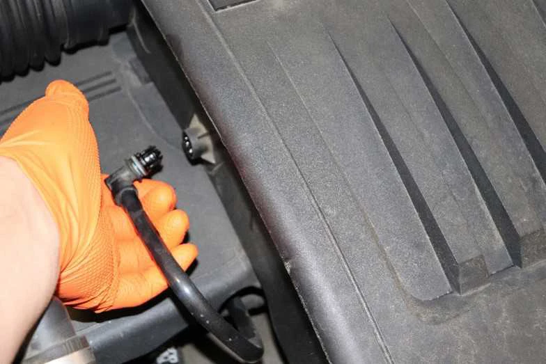
Step 4: Disconnect Heated Oxygen Sensor connector and remove the Oxygen Sensor.
Step 5: Remove the Catalytic Converter Brace between the Catalytic Converter and the engine.
Step 6: Remove 4 nuts securing the Catalytic Converter to the engine, and remove the Catalytic Converter.
Installation
Installation is accomplished in the reverse order of removal. Tighten fasteners as specified below.
Catalytic Converter nuts - 37 lb.ft (50 Nm).
Heated Oxygen Sensor - 31 lb.ft (42 Nm). NOTE: Apply anti-seize compound to threads of Heated Oxygen Sensor before installation.
Exhaust Manifold Bracket bolts - 37 lb.ft (50 Nm).
Exhaust Manifold Heat Shield bolts - 89 in-lb (10 Nm).
Air Cleaner Outlet Duct bolts - 71 in-lb (8 Nm).
Repair Validation
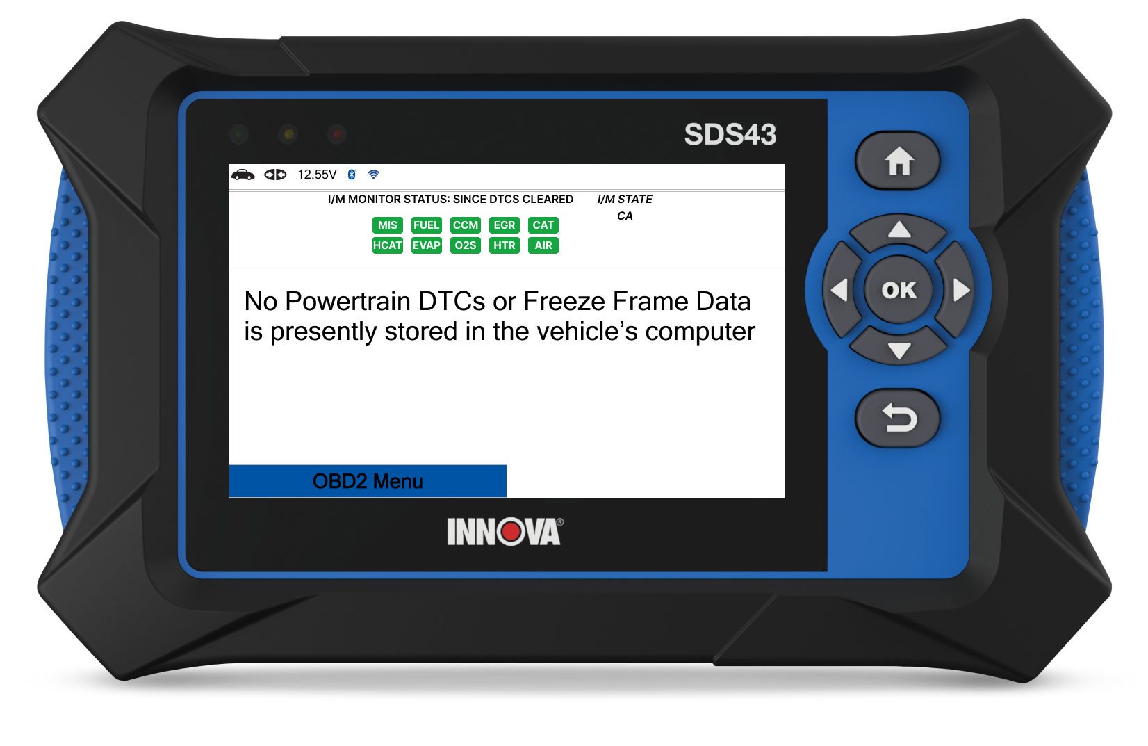
1. Clear Diagnostic Trouble Code (DTC(s)) and Freeze Frame (FF) information.
2. Perform the Key ON Engine OFF (KOEO) and Key ON Engine RUNNING (KOER) tests or follow the On-Board Diagnostics (OBD II) drive cycle requirements for the fault area.
3. Optionally, operate the vehicle within the conditions recorded in the FF data.
4. Check for pending or stored DTC(s). If none are found, the repair is complete.